Module 58, designed to work with the ECU, DSG and CVT. It supports writing on ” OBD ” (the main purpose – tuning), as well as work in BOOT mode (the main purpose – repair) – read and write memory of the processor, as well as external eeprom. For BOOT mode, a direct connection to the gearbox connector is used, but without opening the ECU. OBD work is supported for UDS variants of ECU
DQ200 (0AM) [WR/CK]
DQ250C (02E) [RD/WR/CK]
DQ250E/F (02E) [WR/CK]
DQ200MQB/G2 (0CW) [WR/CK]
DQ250MQB (0D9) [WR/CK]
VL300/V30 (01J/0AN) [WR/CK]
VL381 (0AW) [WR/CK]
DL501/G2 (0B5) [WR/CK]
DQ500 (0BH/0BT) [RD/WR/CK] reading when using a direct connection.
DQ200/MQB/G2 Boot (MICRO) [RD/WR/CK]
DQ200/MQB/G2 Boot (EEPROM) [RD/WR]
DQ250E/F/MQB Boot (MICRO) [RD/WR/CK]
DQ250E/F/MQB Boot (EEPROM) [RD/WR]
VL300/V30 BSL (FLASH) [RD/WR/CK]
VL300/V30 BSL (EEPROM) [RD/WR/CK]
VL381 Boot (MICRO) [RD/WR/CK]
VL381 Boot (EEPROM) [RD/WR]
DL501/G2 Boot (MICRO) [RD/WR/CK]
DL501/G2 Boot (EEPROM) [RD/WR]
1) DQ200 – BOOT – all, OBD – all, except 0AM with K-line
2) DQ250 – BOOT – E/F/MQB, OBD – all
3) DQ500 – 0BT/0BH (no 0DL!) only OBD reading when using a direct connection
4) VL300/V30 – BSL – all, OBD – all, except KW1281
5) VL381 – all
6) DL501 – all
Work on OBD: as usual with other packages, there are no features, in case of recording interruption, you can turn off the ignition, then just record. In the case of “bricking” unsuccessful you can rewrite in the BOOT.
Work BOOT: use a direct connection to the connector of the control UNIT, the switching power supply is carried out either manually or (recommended) by using the scheme of automatic power control, powered by L-line (same PowerBox or converted from KESS). In case of manual control, the entrance to the boot mode may not happen on the first attempt.
Read DQ500: only when connected directly! NOTE: the power supply must be switched manually, while only the ignition must be switched on or off (pin 15), the second contact must be connected constantly!
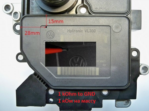
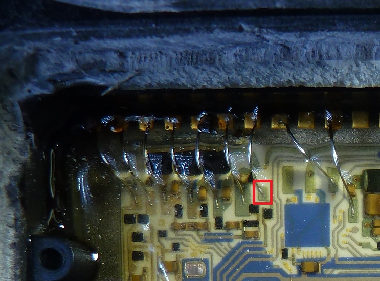
Operation in BSL with VL300 / V30: requires drilling a single hole in the minimum diameter cap in order to insert a needle into it. Needle through a resistor 1 kOhm is connected to the mass. It is mandatory to connect to-line and it is highly recommended to use auto power to quickly “feel” the pin on the Board. The photos below show the drilling location and the point on the Board where the needle should go.
Wiring diagram for the connectors:
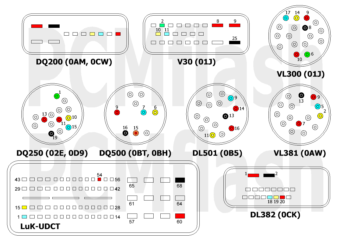
Red – +12в, Black – GND, Yellow – CAN-HIGH, Blue – CAN-LOW, Green – K-Line.
Cloning procedure-read MICRO and EEPROM from “old” box, write MICRO and EEPROM to “new”.
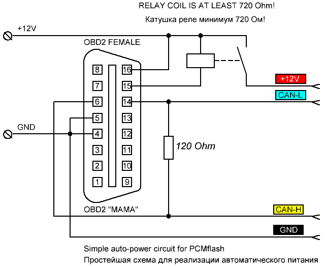
Below is a simple scheme for the organization of auto-feeding and work on the table. Need termination resistor at CAN bus!